Utility Locators work in a number of different modes. The mode that offers the highest level of accuracy at longer ranges is when the line (conductor) that is to be detected can be “Illuminated” using a Tone Generator that sends a low voltage AC signal down the pipe or line. This mode is commonly called the “Direct Connection” mode and requires that the Tone Generator be physically connected to the conductor, such as a pipeline valve, and needs to be grounded, at some distance, perpendicular to the conductor. The frequency of the signal can be set on the Tone Generator and is selected based on the environmental conditions present at the site. Generally with a lower frequency you get a longer range (distance down the pipe and burial depth) and a slightly lower accuracy. Higher frequencies are typically used for shallow burials or areas that are electromagnetically noisy. In applications where burial depths are greater than 2′ and/or there are long distances between the connection point for the Tone Generator and the area where the utility locating is to be attempted, a higher frequency (512Hz) should be chosen. The AC current associated with the Tone Generator’s signal creates an alternating magnetic field around the line that can be detected by the Locator unit’s antennas. The antenna array in the locator is able to very accurately determine the direction the pipeline is running, the locator’s position perpendicular to the direction the line is running and the pipeline’s depth. Utility Locators measure depth to the center of the detected magnetic field and In most cases the center of the magnetic field is at the center of the pipe. In cases where the pipeline splits into two lines that run parallel to one another, the magnetic field becomes more complicated. Because the 2 lines are electrically coupled the Tone Generator’s signal cannot be isolated to one side or the other. This results in a combined magnetic field similar to the one in the figure below. Because the Locator is trying to detect the center of the magnetic field, the locator unit effectively locates the midpoint between the 2 lines. If the lines are shallow or the space between them is far enough apart, there is a potential to identify the two lines individually. Further testing will need to be done to determine under what circumstances resolution of 2 parallel electrically coupled lines would be possible.
When utility locator technology is used in conjunction with survey grade geo-positioning and hydrographic survey equipment a very precise utility location and depth of burial survey can be accomplished, even when the buried utility is crossing under bodies of water.
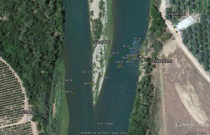
Pipeline Locating Map Example

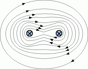
- Combined Magnetic Field Example

http://www.remoteinspectiontechnologies.com/